Q Acoustics has worked closely with some of the world’s leading cable engineers at QED to ascertain the scientific reasoning behind bi-wiring.
Bi-wiring Speakers: An exploration of the benefits
Bi-wireable loudspeakers have been available since at least the late 1980s and it is now quite common to consider bi-wiring speakers. You can easily tell if your speakers are bi-wireable because there will be four connection terminals on the back rather than two. If you have not bi-wired your speakers before, you might be tempted to try because of what you have read in the hi-fi press or online but may also be wondering if the extra outlay on more speaker cable is worth the money.
The idea is that instead of using just one run of cable to each loudspeaker, a separate cable is used for each of the pairs of terminals – once you have removed the little shorting pieces that are normally found connected between them. This means that you will end up using twice as much loudspeaker cable than if you used the traditional single wire method, which has prompted many cynics to coin the phrase “buy” wire to describe the process!
Proponents of the practice point to the obvious sonic benefits they can hear after bi-wiring their speakers, citing the fact that speaker manufacturers make the terminals available, as proof that there must be something in it. Detractors argue that manufacturers are merely maximising the marketability of their products by offering a feature that costs little extra to implement but probably doesn’t make any sonic difference. They also point out that there is no real published evidence to prove that the practice makes any audible difference, whereas the bi-wire enthusiasts theorise that by separating the high and low frequencies into different wires, distortions caused by interactions between them can be eliminated.
Bi-wiring is then, quite a controversial subject. Is it a worthwhile sonic upgrade for your hi-fi or just a clever marketing ploy by the cable companies to make you buy twice as much cable? We decided to do some research to see if an authoritative answer could be given to this subject once and for all.
How are normal loudspeakers wired up to an amplifier?
In Fig. 1, a single speaker cable is shown connecting the output terminals of one channel of an amplifier to a loudspeaker. The loudspeaker itself is of the non-biwireable, 2-way type, having a
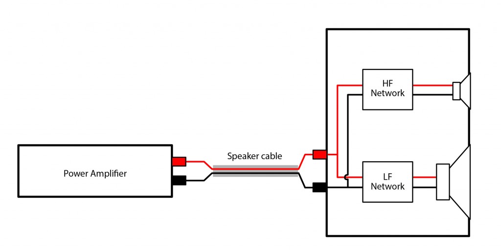
Fig 1 Traditional single wire method
small driver, also called a tweeter, to reproduce frequencies above e.g. 2kHz (HF) and a large driver (or woofer) to reproduce frequencies below this point (LF). Sound reproduction duties are divided like this because it is not very easy or cost effective to design and manufacture a single drive unit which is capable of reproducing the entire audible sound spectrum with equal fidelity at all frequencies. A passive electrical circuit (represented by the two boxes labelled HF network and LF network) is used to filter the current taken from the amplifier so that only the high frequencies can pass through the tweeter and only the low frequencies can pass through the woofer.

Fig 2 Crossover Response Curves
The incoming current is split between the two parts of the crossover network inside the loudspeaker so that only one pair of terminals is presented to the outside world. This circuit cannot create a steep cut-off point at the chosen turn over frequency but instead produces a more gradual attenuation above or below the chosen frequency. In the graph above you can see the point where the two curves meet (blue for woofer, red for tweeter), represents a frequency where both drivers contribute equally to that particular frequency. This is known as the “crossover point” and for this reason the passive circuit itself is known as a “crossover”. Note that the total output of the combined drivers (black) remains essentially flat because this crossover has been correctly designed so that the combined output of both drivers is the same as if they were a single perfect driver.
How does current flow in a single wired speaker?
Consider the red terminal on the back of the amplifier. This is where the amplifier can create a large potential for current to flow. A large number of charges build up here and these charges have only one function in life and that is to find their way to the black amplifier terminal. If a path or circuit exists then the charges will start to move towards this terminal creating an electrical current. If during this journey they move through a loudspeaker coil then they can do useful work for us by creating sound. The amplifier is a power amplifier because (within its capabilities) it can provide all the current demanded of it by the loudspeakers and still maintain the same potential for current to flow at its red terminal. Note that this current is demanded or taken by the loudspeakers and NOT sent by the amplifier. It can be useful to use every day examples to help us picture how the current flows. Charges do not flow round the circuit one at a time; rather they behave like a nose-to-tail traffic jam on the motorway. A single charge anywhere in the queue will only move if the one in front moves, so if there is no path to the black terminal for a charge right next to it then a charge all the way at the back of the queue just emerging from the red terminal will be stationary also.
Now imagine the charges provided by the amplifier are divided into low frequency and high frequency ones (or slow and ponderous trucks and fast and agile motorbikes in our traffic jam analogy). Once the circuit is made all the traffic starts to flow out of the red terminal of the amplifier using the single speaker cable, into the red terminal of the loudspeaker where they get separated by the crossover, do the work in their respective loudspeakers and then join back up at the black terminal of the loudspeaker and use the single speaker cable again to reach their ultimate goal – the black amplifier terminal! Note that in the above example both types of current, high and low frequency have to use the same speaker cable. Also there is no waiting for the first charge to make it all the way around – it’s a permanent traffic jam remember? As soon as the green light is given traffic is already flowing at the black amplifier terminal.
How are bi-wireable speakers wired up to an amplifier?
Fig. 3 shows how a typical biwireable speaker is connected to an amplifier. It has four terminals instead of two, one pair for the HF network and one pair for the LF network. Two speaker cables are used to connect the HF terminals and the LF terminals to the same pair of terminals on the amplifier.
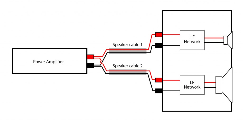
Fig 3 Bi-wiring connection diagram
How does current flow in the bi-wired speaker cables?
Consider the above circuit before the amplifier provides any potential at its output terminals. The traffic jam will be stationary – it’s nose to tail trucks and motorbikes all the way from the amp, down both speaker cables, inside each of the LF and HF networks and back to the amp again. Nothing is moving. Suddenly the amplifier gives the green light. In the HF network are a set of bollards too close together for trucks to get through – only motorbikes can slip through. So in speaker cable 1 only the motorbikes will be moving. Yes, the trucks are still there but they are all parked – can’t move. In electrical terms only high frequency currents will be flowing in speaker cable 1. Even though the filter circuitry is at the far end of the cable there will be no low frequency current present in the whole of the cable leading up to that point. This is a hard concept to grasp first time. If you get it great, read on. If not then keep re-reading to this point until you do.
The same goes for speaker cable 2, except in the LF network there is 2 foot six feet of water which the motorbikes cannot negotiate so they are all stationary, whereas the trucks can plough on through. So, in speaker cable 2 only the low frequency current will be flowing.
Effectively, as if by magic, we have separated the high and low frequencies and sent them down different cables to the correct driver. If you are still asking “but how do the different frequencies know which way to go?” or saying “ don’t talk rubbish, both cables have all the frequencies in them the same, right up until the crossover” – then try re-reading the above until you understand it.
What are the benefits of separating high and low frequency currents like this?
The traffic jam analogy is helpful to understanding the reason why current flow in the two
interconnecting cables is different but of course it’s not really how current flows in the cables. For one thing we are dealing with alternating current, so the traffic is flowing in both directions alternately. The mechanism is a bit (but only a bit) more like Newton’s cradle, where the first ball imparts an impulse to the next and although the balls themselves don’t actually move very far or fast at all, the impulse itself moves incredibly quickly through the row of balls. In the speaker cable, current flows because spare electrons in the crystal lattice swap places and because of the electric field provided by the amplifier they do this in a net direction rather than randomly, and so a current flows. The electric field affects all the spare electrons in the conductor at the speed of light so there is no waiting for the electrons to make their way through the cable at their relatively slow drift velocity (typically just 1mm/s), the imperative to move is imparted much faster. The theory in favour of bi-wiring is that if both low and high frequencies are present in the same conductor unwanted distortions can be created.
Going back to our Newton’s cradle analogy, if the balls are all stationary and then one is lifted and released the impulse travels quickly through the row and the end ball pings off in time “t”. If we now set all the balls swinging at a low frequency first and then repeat the same process the end ball pings off in a different time “t2”. This is analogous to the low frequency and high frequency signals being present in the same cable; they have combined within the transfer medium to create a new frequency which was not in the original signal in a process known as intermodulation. Wherever there is non-linearity in a system which carries multiple different frequencies there will be amplitude modulation made up of the sum and difference of the original frequencies and in addition, harmonics of these sum and difference frequencies. Unlike some types of harmonic distortion this type of distortion is not nice to listen to and although non-linearity in good hi-fi equipment is generally very small, it is enough to produce intermodulation distortions which are bothersome to the listener.
If intermodulation distortion is present in the cable, could we try to measure it?
Now we are close to proving that bi-wiring has some useful sonic benefit. We have accepted that the two cables carry different signals and that by keeping them separate we may have prevented the production of otherwise harmful intermodulation effects. If it was possible to measure intermodulation distortion in a single wired speaker and then to measure a reduction of the same in that speaker once it was bi-wired, we could make a really good case for the procedure.
Some work on this subject has been published1 by the Audio Engineering Society. A split band spectral analysis methodology is described in the paper which uses a ten tone system split into two bands, one high and one low, starting at 5kHz and 100Hz respectively. These impulses and their attendant frequencies were chosen carefully so that any frequencies measured outside of these fundamentals could be attributed to intermodulation and cross-modulation effects rather than being masked by harmonic distortion (Risch, 1998). Using the same methodology as described in the paper we generated a similar test tone and conducted our own investigation to see if we could measure any differences between single wired and bi-wired speakers.
A current probe was used to measure the frequencies present in each of a single wired and a biwired tweeter and bi-wired woofer cable. Figure 4 below, shows the multi-tone test signal we created and burned to a CD, which consists of five frequencies at and above 100 Hz and a second five tone band at and above 5 kHz, as it emerges from the CD player.
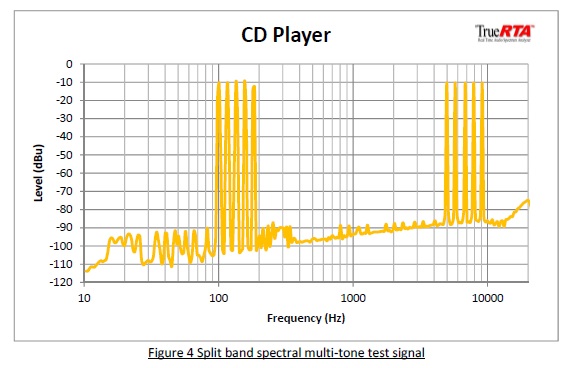
The high frequency tones can be seen as five distinct peaks in the graph (yellow) at about -10dB. The low band tones show five clear peaks at or above 100Hz. Note the very low background noise level of at most -90dB between the two bands.
Compare this with the current probe measurement of a single wire speaker cable (blue) shown in figure 5.
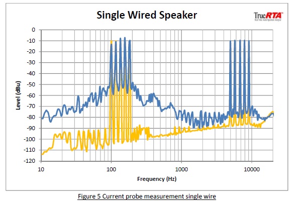
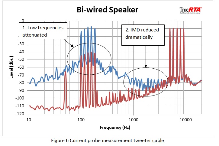
Intermodulation products have raised the distortion and noise within the cable in some cases to a level just 40 dB below the fundamental tone frequencies. Compare this with a measurement taken from the bi-wired tweeter cable, attached to the same speaker, tested under the same conditions (red) in Figure 6.
Firstly, it is gratifying to see that the bass frequencies have been attenuated in the cable by 35dB which proves that high and low frequencies have been effectively separated into the different cable runs in our bi-wire system. Secondly at and above the typical cross-over frequency of 1 – 2 kHz, the intermodulation distortion has been reduced by up to 30dB.
Now let’s look at the woofer cable (Green). Again, the high frequency component has been reduced in the woofer cable, proving our assertion that the frequencies “know which way to go” in a bi-wire system.
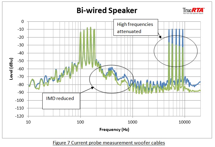
There has been less of a dramatic improvement in the intermodulation products in the woofer cable but they are still there. This can be explained by the fact that the tweeter currents are not as large as those in the woofer cable, so the IMD they produce is not as big.
Conclusion
We have discovered that if your speakers have four binding posts then you may take advantage of the bi-wiring option and that you will need twice as much cable as before. We theorised and proved by measurement, the counter-intuitive notion that the high and low frequencies travel only in their designated cables. We have also shown by measurement that the theory that this would reduce intermodulation distortion caused by non-linearity in the speaker system is proven.
In light of the above evidence it would be sensible to conclude that where the opportunity exists and funds allow, bi-wiring should be explored as an option for improving the performance of any high fidelity loudspeaker system.
References
1 Risch, Jon M . 1998. “A New Class of In-band Multi-tone Test Signals.” Audio Engineering
Society
Notes
The test tone CD was played using an all in one CD player/amplifier set at half volume into a pair of floor-standing speakers. The current probe measurements were analysed using TrueRTA via a Tascam US144 USB audio interface. The single wired measurements were taken with two runs of speaker cable wired in parallel (speaker shorting pieces in place) and the bi-wired measurements were taken using the same arrangement with the shorting pieces removed. In this way both measurements used the same cross-sectional area of cable to eliminate any effect of lower resistance on our measurements.


