


ANALOGUE
With a vast array of technologies and our 40+ years in the specialist cable market, we produce cables to suit every budget to maximise the potential of your beloved system. With a vast array of technologies and our 40+ years in the specialist cable market, we produce cables to suit every budget to maximise the potential of your beloved system.
DIGITAL
Whether you’re connecting your TV to a sound bar or music server to a DAC, QED has a digital cable to meet your requirements. Our cables are tried and tested to ensure you get the best performance from your digital sources.
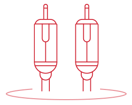
PHONO TO PHONO
When connecting your analogue sources such as your CD player or turntable to your amplifier, here at QED, we have a cable to suit your system. From our entry level Profile cable through to our flagship Signature Interconnect.
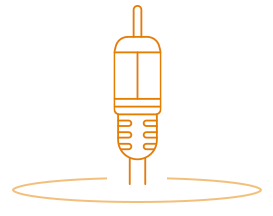
XLR
Using our unique Tri-Conductor technology and Neutrik XX-14 balanced plugs, our XLR cables offer the cleanest possible sound from a specialist XLR cable, whilst also incorporating our Ferrite insulation to eliminate timing errors.
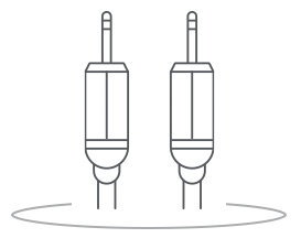
DIGITAL COAXIAL
An alternative to optical, our premium digital coaxial cables use a specially designed cable cordage and unique plug design to achieve the precise signal characteristics required for high resolution and multi-channel audio.
USB A-B
With our high end USB A-B we isolate the power and data conductors preventing any potential cross talk, therefore meaning less jitter and an enhanced audio performance.
USB A-B MICRO
For use with Laptops/Computers and portable headphone amps/dacs, the QED reference USB A-Micro B uses our Ferrite insulation to reduce Jitter, as well as isolating the data and power lanes for a cleaner overall signal.
USB A-MINI B
Triple magnet screening and 24K gold plugs makes our Performance USB A-Mini B the best in its class.
JACK TO PHONO
Connecting your mobile device/tablet to your audio system has never been easier with our 2 step 3.5mm jack for a simpler connection.
HDMI
Using our in house HDMI testing facility, QED have designed premium HDMI cables to suit any budget. From our flexible and slimline profile to our exceptional Reference HDMI with its BandPass filter technology to reduce Jitter to Ultra low levels
OPTICAL
For all of your Optical needs, QED has an optical cable for you. For the more advanced, high bandwidth signals, Reference Optical Quartz uses glass technology to accurately send the information from source to receiver.
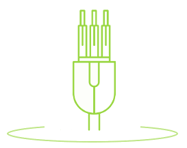
ETHERNET
The most common type of cable used for connecting products on a wired network. This cable connects wired devices together to the local network for file sharing and Internet access.
SUBWOOFER CABLE
Using technologies from our analogue cables such as complimentary conductor technology, your subwoofer will always perform to its best capability.
Sound of Science
We have always believed that the most sophisticated sound receiving device of all time is the truly incredible human ear, and we both acknowledge and are challenged by how this wonderful instrument can detect the most minute of sonic differences that we currently struggle to measure. Exhaustive listening tests therefore remain an essential element in turning a very good cable in to an exceptional one.
The Genesis Report
The once humble loudspeaker cable has seen a meteoric rise in importance in recent years. Previously almost an afterthought, cables are now crucial high-technology audio components in their own right, though often cloaked unnecessarily in mystery and intrigue.
The Genesis Report II
In 1995 we published the Genesis Report on loudspeaker cable design. In that document we established design principals, scientifically proved, which are as valid today as they were 12 years ago. This longevity is an unequivocal endorsement of both the quality and depth of that original scientific research. The Genesis Report laid the foundations on...
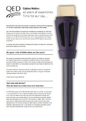
HDMI Cables Matter
Recently there have been discussions on television and the internet suggesting it's not worth upgrading to high quality digital audio and HDMI cables. We have our say...
The Genesis Report II
A Underlying Principle of Cable Design

Preface
In 1995 we published the Genesis Report on loudspeaker cable design. In that document we established design principals, scientifically proved, which are as valid today as they were 12 years ago. This longevity is an unequivocal endorsement of both the quality and depth of that original scientific research. The Genesis Report laid the foundations on which we based all our subsequent loudspeaker cable designs, from QED Original, though to Profile, SA-XT, X-Tube and of course Genesis.
Genesis II embraces the modern A/V and digital world we all now inhabit. It explains how many of the principles that apply to analogue cable design are equally applicable to this new digital age.
I believe it makes fascinating reading.

Bob Abraham
Co-founder QED
Contents
- Introduction
- The Cable's Role
- Some Theory and Interesting Facts
- Cables and the Importance of Characteristic Impedance
- Conductor Chemistry
- In the Digital World
- The Future
- Summary
Introduction
Around the world, the debate continues amongst both audio and videophiles, as to which cable designs offer the best performance.
QED, an established market leader in this field, has won many coveted awards for its high performance audio and A/V cable products. Key to this success has been the application of strong engineering principles, coupled with extensive test and measurement of both our own and competitor's products.
In this report, we re-visit some of the areas covered in QED's original 1995 'Genesis Report' and also investigate in more detail the underlying principles of how cables work. Included are the various fundamentals relating to signal transmission that are scientifically intriguing and also central to developing cables that really do perform better, for both Sound and for Vision.
The Cable's Role
Ideally every cable should transfer a signal between two components with zero loss and distortion. However, in the 'real' world this is not possible, because subtle changes occur in the signal, which result in readily perceived changes to both sound and video quality. The degree of change is determined directly by the design of cable being used.
Maximising 'real' world cable performance requires an understanding of the signal transmission process and the engineering tools available, to ensure the signal arrives in the best possible condition.
Some Theory and Interesting Facts
Cables appear to be very simple components in both their construction and operation. However, once you venture beneath the surface, things become a lot more interesting.
Conductors:
Metal conductors such as copper work very well. This is because their structure supports a huge number of free electrons, which are not locked into the copper's atomic structure and are therefore free to move.
A metal conductor consists of metal ions arranged in a regular pattern called a crystal lattice with free electrons moving in the spaces between the ions. The movement of free electrons is random and very fast, but with a net effect of zero current flow. Due to thermal energy, free electrons move about randomly and jump between atoms. There are an incredibly high number of free electrons available to move, in just 1cm3 there are approximately 8.47x10²² electrons. When a potential difference exists across the metal conductor and a current flows, electrons drift along at a velocity dependent on the current, size and type of conductor. The resistance of the conductor is due to collisions between the free electrons and metal ions in which some of the kinetic energy possessed by the electrons is transferred to the ions. This causes the lattice to vibrate, converting this electrical energy to thermal energy.
Copper in particular is an excellent conductor, having a high conductivity ( ) because its outermost electrons have a largely free mean path, about 100 atomic spacings between collisions. The electrical resistivity ( ) of the conductor is inversely related to this mean free path. Silver has the lowest resistivity with Copper and Gold following closely behind. Copper is far more abundant and therefore used more extensively than silver.
Unfortunately all metal conductors possess resistance which opposes the movement of electrons and dissipates some of the available energy as heat. Resistive effects on system performance were covered extensively in the 1995 Genesis Report on speaker cables, but equally apply to video cables (for example those used for HDMI transmission) where a cables resistance will dramatically impact its ability to transfer high frequency signals over a long distance.


Superconductors
Superconductors are conductors that have no electrical resistance and conduct electricity with zero loss, thus once an electrical current has started to flow in a superconducting ring it will do so forever. Superconductors are also perfectly diamagnetic (i.e. they repel a magnetic field); this property was discovered in 1933 and is named the Meissner effect.
The difficulty with using superconductors is the very low temperature required for the material to super conduct. At the time of writing the superconductor with the highest critical temperature ever recorded is Mercury Barium Thallium Copper Oxide which has a critical temperature of 139ºK (-210ºF or -134ºC). So it looks as if we will wait some time until a viable superconducting cable works at room temperature.
With all this emphasis on metal conductors one might assume that they do all the work, but is this really the case?
How Does the Signal Travel and How Fast?

For a 1 metre interconnect it takes the free electrons around 100 seconds to travel from one end to the other. This is a significant time and clearly we do not wait that long for music or video to appear, so another transmission mechanism must be occurring.
Thankfully a Scottish mathematician and theoretical physicist named James Maxwell (1832-1879) provided an answer through his work on electromagnetic waves. Signals do in fact travel down cables as an electromagnetic wave and this wave does travel at a very high velocity. If the metal conductor were perfect virtually all the energy would be transferred from one end of the cable to the other in the electric and magnetic fields around the conductor.
The energy flux vector described by an English physicist John Henry Poynting (1852-1914) shows that the energy flow and its magnitude is derived by considering conservation of energy. That is, the total energy in the system is constant, and the fact that the magnetic field can do no work.
S = E x H
Where 'S' (energy flux) = Electric field x Magnetic field

Furthermore electromagnetic wave theory shows that when conductor pairs are configured, the majority of the energy will propagate in the space between the conductors (Figure 1).
These fundamental principles apply to all types of signal transmission, whether low frequency Audio or high frequency Video, Digital or Analogue, even AC mains transmission across the national grid, the signal energy travels in the fields around the conductor and the free electrons only carry a small fraction of the energy travelling along the cable.
Importance of Dielectrics
Once it is understood the space around the conductor carries the signal energy, it becomes obvious the material in that space is a very important component of cable design.
The dielectric space around the conductor has a direct effect on the propagation of the electromagnetic wave along the cable, particularly in terms of its speed, energy storage and energy loss. Dielectric loss increases linearly with frequency, with energy being dissipated as heat. The speed of the signal, velocity of propagation (v) can be shown to be:
Velocity of propagation ? = 3x10⁸/??r?r m/s
Where ?r = relative permeability (degree of magnetisation in repose to a magnetic field)
?r = relative permittivity (ability to 'permit' an electric field)
At this point, it is interesting to look at the mechanism responsible for dielectric loss. In the non conducting dielectric the electrons are bound to the atoms; however when an electric field is present, the orbit of the electrons becomes distorted, as the negatively charged electrons become attracted to the positive conductor. The movement of these electrons requires energy from the signal which is ultimately dissipated as heat within the dielectric. The better the dielectric the easier the atoms (not electrons) move and the lower the resulting loss
Electromagnetic Fields and More on Resistance
Unlike the electric field, the magnetic field does radiate from within the conductor, rising to a maximum at the conductor dielectric boundary (Figure 3).

It is also worth considering at this point that the external field energy lost, due to the resistance of the cable, results in a loss energy field travelling in the copper conductor. Importantly this energy propagates through the copper at a much slower speed than the external field and is dependent on the frequency of the signal. Electromagnetic fields travel most quickly through poor conductors, which is why radio signals travel at the speed of light through outer space. As the conductivity increases, the speed of the signal decreases. If the conductor were perfect (no loss) then the electromagnetic field would be entirely reflected when it reached the conductor surface. Metals have a refractive index just like glass.
In the real world the majority of the external field is reflected, however a small fraction penetrates the imperfect conductor where it is attenuated quickly. There is a characteristic penetration distance, which is often referred to as the Skin Depth.
The depth of penetration is defined as:
The depth of penetration is defined as ?Z=?(2/?o??)
Where: ?o =Permeability, ?= Conductivity, ?=2?f(frequency)
It is therefore desirable to reduce the variation in field across the conductor's area to ensure that a uniform current flow is maintained at all frequencies, otherwise the varying field patterns within the conductor act like a selective filter. (The results of the tests in the 1995 Genesis report still hold true, however when developing very low resistance cables skin depth needs to be considered, as it was for the design of the Genesis speaker cable)
The velocity of the signals propagation in the conductor is also dependent on the transmission frequency; the higher the frequency, the faster the transmission and the lower the frequency, the slower the transmission.
These factors were instrumental in QED developing its X-TubeTM technology, which takes into account the requirement to minimise resistance whilst simultaneously ensuring the conductor is not subjected to a wide variation in penetration by the electromagnetic field. (The result being a clean and dynamic sound)
It is also important to note that negative cable effects go largely unnoticed when their performance is measured using conventional test techniques, such as sinusoidal test tones. Transient response testing is much more revealing and was used to test speaker cables in the original Genesis report. This technique can be applied equally well to low level signal cables to objectively assess performance.
Cables and the Importance of Characteristic Impedance
This area is often misunderstood. For low frequency audio signals (20Hz to 20kHz) traveling over a short distance, the characteristic impedance of the cable has virtually no impact on the energy transfer between the transmitter (amplifier) and receiver (speaker), and therefore is not a consideration in speaker cable design. However, this changes once the wavelength of the electromagnetic wave, traveling down the cable, becomes shorter than the length of that cable. Designing a high performance cable that carries an RF (Radio Frequency) video signal therefore requires considerable care to ensure that signal energy is not lost.
Characteristic impedance is not constant and is dependent on the frequency of the signal being transmitted. At low frequencies the cables Resistance (R) and Conductance (G) define the impedance, whereas at high frequencies it is the Inductance (L) and Capacitance (C).
The general equation for Characteristic Impedance (Zo) is expressed as:
Zo = ?(R + j?L)/(G + j?C)
Where ?=2?f(frequency) and j=Imaginary (vector) part of the equation
The Characteristic impedance is determined by the physical dimensions of the cable's conductors, their spacing and the relative permittivity (_r) of the dielectric.

When designing interconnects for use with high frequency signals the connector impedance is critical. Whilst developing the QED 'TTV' range of aerial cables, TDR analysis showed that many so called 'high end' connectors did not have the correct characteristic impedance. This results in high levels of energy being reflected back to the source. When signal levels are particularly low, as is the case with antenna feeds, the outcome is poor picture quality and fewer stations on the channel listing!
Conductor Chemistry
Conductor chemistry is very important for the establishment of high electrical conductivity. The presence of elements such as silicon, magnesium and phosphorus all decrease the electrical conductivity. The most widely used copper is electrolytic touch pitch (ETP) copper, which consists of extremely high purity metal and oxygen in the range of 100-650ppm (parts per million). Oxygen is used as an alloying element and also as a scavenger in reacting with most of the impurities in the copper. Adding around 0.02% oxygen to ETP copper increases its conductivity. Oxygen Free Copper is produced primarily for its ability to be heat treated without embrittlement, for ease of use when welding and brazing. The acronym for the term, oxygen-free high conductivity copper OFHC(TM) is a registered trademark of Phelps Dodge Specialty Copper Products. OFHC is a highly refined grade of copper that contains almost no oxygen or other impurities.
Certified oxygen free high conductivity copper contains a minimum of 99.99% copper making it the purest metal in common use. The IACS (International Annealed Copper Standard) gives a percentage ranking for conductivity. ETP coppers fall typically within the range 100-101.5% IACS and OFHC around 102.4% IACS.
In the Digital World
Jitter and Crosstalk
Jitter is a term used to describe the time variance by which a digital signal arrives at the receiver. All metal cable links have a finite bandwidth which attenuates the high frequency components of the digital signal. A transition delay occurs (that is the delay in which the receiver detects a '1' or '0') which varies depending on the pattern of the digital signal. Digital equipment normally has a built in tolerance to jitter, however it is not always effective, depending on the frequency of the incoming jitter. In such cases the cable induced jitter is transferred to the recovered clock signal, as is the case with an SPDIF signal. For long cable lengths the digital signal 'eye' closes and reduces in size, ultimately resulting in a failure of the link (Figure 5).

The Future
New technologies place increasing demands on the transfer of information between audio and video products. To realise the very best performance, cables are required to carry data more effectively at ever increasing frequencies. This means designers are constantly investigating new materials and configuration geometries to obtain the desired performance objectives.
The emphasis today is undoubtedly on digital transmission, where higher speed signals quickly reveal the limitations of poorly designed and constructed cables. Digital systems are sensitive to signal loss and degradation, so cables will continue to play a vital role in maintaining audio and video quality.
Wireless technology has improved considerably in recent years bringing a big improvement in connection convenience. Wireless however is always likely to lag behind cable in terms of bandwidth, making it less suitable for the demands of very high performance applications. Optical cables are more likely to replace conventional metal cables in the longer term and have already done so in many areas of telecommunications.
QED is continually researching new materials and constructions to ensure their products offer technically advanced interconnectivity solutions. Measuring, listening and viewing the results of this research will continue into the future.
Summary
The fundamental principal of electromagnetic signal transmission via a cable remains unchanged, whether it is applied to audio or video signals and in both the digital and analogue domains. Whilst technology is unquestionably advancing rapidly, the physics of transmission is constant. We can however, continue to refine and improve our understanding.
It is vitally important that a cable's characteristics are designed to match the specific application required, in order to minimise losses and changes in the signal being transmitted. It is not sufficient to consider purely the cable, the connectors must also be correctly designed to minimise electromagnetic energy being reflected back down the cable. Changes in impedance due to manufacturing tolerances have to be minimised. This is particularly important at RF frequencies.
The real world mechanisms, by which the electromagnetic signal loses its energy, and the subsequent reduction in velocity of the signal energy propagating through the conductor and dielectric, are important considerations when determining the conductor configuration. When designing cables for high performance A/V systems, interaction between conductor pairs is more relevant than ever and requires careful attention to ensure minimal signal corruption.
Lowering cable resistance and minimising impedance at high frequencies has proven to be beneficial, under both technical and subjective assessment, applying equally to low frequency speaker cables as well as high frequency video cables. Cable geometry, which is way the different materials are configured, is central to achieving good cable performance. The best materials incorrectly configured, will never outperform a correctly configured cable using lower grade materials. The best solution is of course to use optimised geometry with high grade materials.
At QED, our understanding of the physics of what is happening within a cable enables us to make truly informed decisions about cable design. We can devise intelligent solutions, which will effectively convey audio and video signals in optimum condition.