


ANALOGUE
With a vast array of technologies and our 40+ years in the specialist cable market, we produce cables to suit every budget to maximise the potential of your beloved system. With a vast array of technologies and our 40+ years in the specialist cable market, we produce cables to suit every budget to maximise the potential of your beloved system.
DIGITAL
Whether you’re connecting your TV to a sound bar or music server to a DAC, QED has a digital cable to meet your requirements. Our cables are tried and tested to ensure you get the best performance from your digital sources.
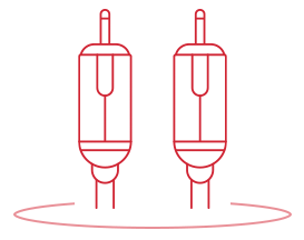
PHONO TO PHONO
When connecting your analogue sources such as your CD player or turntable to your amplifier, here at QED, we have a cable to suit your system. From our entry level Profile cable through to our flagship Signature Interconnect.
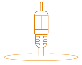
XLR
Using our unique Tri-Conductor technology and Neutrik XX-14 balanced plugs, our XLR cables offer the cleanest possible sound from a specialist XLR cable, whilst also incorporating our Ferrite insulation to eliminate timing errors.
DIGITAL COAXIAL
An alternative to optical, our premium digital coaxial cables use a specially designed cable cordage and unique plug design to achieve the precise signal characteristics required for high resolution and multi-channel audio.
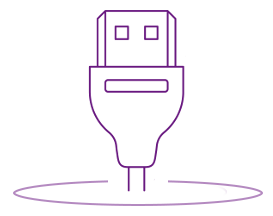
USB A-B
With our high end USB A-B we isolate the power and data conductors preventing any potential cross talk, therefore meaning less jitter and an enhanced audio performance.
USB A-B MICRO
For use with Laptops/Computers and portable headphone amps/dacs, the QED reference USB A-Micro B uses our Ferrite insulation to reduce Jitter, as well as isolating the data and power lanes for a cleaner overall signal.
USB A-MINI B
Triple magnet screening and 24K gold plugs makes our Performance USB A-Mini B the best in its class.
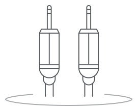
JACK TO PHONO
Connecting your mobile device/tablet to your audio system has never been easier with our 2 step 3.5mm jack for a simpler connection.
HDMI
Using our in house HDMI testing facility, QED have designed premium HDMI cables to suit any budget. From our flexible and slimline profile to our exceptional Reference HDMI with its BandPass filter technology to reduce Jitter to Ultra low levels
OPTICAL
For all of your Optical needs, QED has an optical cable for you. For the more advanced, high bandwidth signals, Reference Optical Quartz uses glass technology to accurately send the information from source to receiver.
ETHERNET
The most common type of cable used for connecting products on a wired network. This cable connects wired devices together to the local network for file sharing and Internet access.
SUBWOOFER CABLE
Using technologies from our analogue cables such as complimentary conductor technology, your subwoofer will always perform to its best capability.
Sound of Science
We have always believed that the most sophisticated sound receiving device of all time is the truly incredible human ear, and we both acknowledge and are challenged by how this wonderful instrument can detect the most minute of sonic differences that we currently struggle to measure. Exhaustive listening tests therefore remain an essential element in turning a very good cable in to an exceptional one.
The Genesis Report
The once humble loudspeaker cable has seen a meteoric rise in importance in recent years. Previously almost an afterthought, cables are now crucial high-technology audio components in their own right, though often cloaked unnecessarily in mystery and intrigue.
The Genesis Report II
In 1995 we published the Genesis Report on loudspeaker cable design. In that document we established design principals, scientifically proved, which are as valid today as they were 12 years ago. This longevity is an unequivocal endorsement of both the quality and depth of that original scientific research. The Genesis Report laid the foundations on...
HDMI Cables Matter
Recently there have been discussions on television and the internet suggesting it's not worth upgrading to high quality digital audio and HDMI cables. We have our say...
The Genesis Report
Contents

- Introduction
- The Cable's Role
- Basis of Assessment
- Real Effects On System Performance
- Skin Effect
- Inductive Effects
- Audibility of Phase Shift
- Peaking Due to Inductance and Capacitance
- Dielectrics
- Cable Conductance
- Effects of Capacitance
- Capacitance Versus Inductance
- Acoustic Crosstalk
- Transient Performance
- Cable - Induced Distortion
- Multi - Strand Vs Single Core Distortion
- Characteristic Impedance
- Directionality
- Conclusions
- Genesis - The Outcome
Introduction
The once humble loudspeaker cable has seen a meteoric rise in importance in recent years. Previously almost an afterthought, cables are now crucial high-technology audio components in their own right, though often cloaked unnecessarily in mystery and intrigue.
There is now a vast choice of diff e rent cable types, designed to suit every need. Unfortunately, consumers are now confronted by a bewildering array of claims and counter- claims, turning what should be a straight forw a rd purchase into something of a nightmare! This situation is not helped by the mysticism and pseudo-science which is all too often used by some marketing departments.
This technical guide is a summary of in-depth scientifically-conducted research, with measurements and listening tests, carried out by QED into loudspeaker cable effects. Our aim was to develop new ranges of high-perf o rmance cables based on the results of these investigations and the current QED loudspeaker cables were developed as a direct result. Many lessons were learned, which have also influenced our interconnect cable design.
The listening sessions were vital: QED engineers are all too aware that measurements alone are not the whole story. It would be tempting to claim that they tell you everything, though this is clearly not the case. On the other hand, if any cable introduces measurable errors and distortions as a result of being inserted between the amplifier and loudspeaker, it obviously cannot reproduce music accurately.
QED believes cables should be as accurate, transparent and neutral as possible and it is with this credo that our cable development is undertaken, based on Genesis and guided by exhaustive listening evaluations.
The Cable's Role
At first glance the role of loudspeaker cable would appear to be rather unglamorous, simply conveying the signal between amplifier and loudspeaker. In practice, though, diff e rences in cable perf o rmance can readily be discerned by most listeners - though some diehards still deny even the possibility. Clearly there are factors in cable design and construction which influence sound quality.
Bearing in mind that no component can improve on the analogue signal passing through it (but can only change and degrade it) the ultimate role of any loudspeaker cable should clearly be to transfer the signal energy between amplifier and loudspeaker without loss.
Basis of Assessment

Resistance (R), Capacitance (C), Inductance (L) and Conductance (G).
Most power amplifiers are amplifying devices which achieve fidelity by comparing their output signal with their input. This is called 'negative feedback', or NFB. Any error appearing at the output of a NFB amplifier is effectively corrected by the amplifier automatically applying the opposite error at its own input. As can be seen from the diagram in Fig.1, an NFB amplifier can only attempt to correct errors that appear at the point of feedback. Errors at the loudspeaker input due to the influence of the cable remain uncorrected: the cable is beyond its jurisdiction.
Some NFB amplifiers have been designed to take their feedback from the loudspeaker terminals in an attempt to counteract cable effects, though this type of configuration is very rare. One objective assessment of a cables perf o rmance would therefore be to compare its input (at the amplifier output) to its output (at the loudspeaker input). Any difference amounts to degradation of the signal.
Real Effects On System Performance

The two graphs shown in Fig. 2 and Fig. 3 a re frequency responses. The upper trace was taken at the amplifier's output and the lower curve was measured 'after' the cable (at the loudspeaker's input terminals). There are clear differences in performance between the two cable types.
The lower of the two curves in Fig. 2 is for a very low loop resistance ribbon cable (sample 10 in our tests), while Fig. 3 shows the effect of a dual-stranded solid-core cable (sample 7). The ripples in the curve are due to the variations in load impedance of the loudspeaker system within the audio bandwidth influencing the voltage 'dropped' across the cables impedance at different frequencies.

The loss in the cable is effectively the difference between the upper and lower curves in both Fig. 2 and Fig. 3. Clearly, there is a greater loss due to the solid core shown in Fig. 3 due to its greater DC resistance. This is not merely academic, because the overall frequency response of the loudspeaker will be modified by these variations (amounting to as much as -0.8dB at 200Hz for Fig. 3). The resultant responses shown in both curves are typical of a bass reflex (ported) loudspeaker system using a steady-state sinewave input signal. Real signals are non-sinusoidal (comprising many frequencies simultaneously) and the loads presented by loudspeakers will be complex (complex meaning that current and voltage are not always exactly in step, or in phase). As a consequence, there will be a far greater dynamic amplitude loss across the cable when playing music than would at first be inferred by examining these steady- state curves.
Given this clear evidence that low resistance is necessary to ensure the flattest possible frequency response with real-world loudspeakers, it is surprising that there has been a trend away from low-resistance cables to higher resistance solid-core types. One of the major reasons quoted in manufacturer's marketing materials has been the claimed reduction in skin effect obtained from the use of low-cross- sectional- area solid- core cables.
Skin Effect
Skin effect is a phenomenon normally associated with high- frequency transmission lines. When an alternating current flows through a conductor, an electromotive force (EMF) is induced due to the changing magnetic flux within the conductor. This causes the current density to decrease at the centre of the conductor compared to that near the outer surface. In effect, the area through which current flows is reduced, with current diverted from the core. The result of skin effect is a rise in cable impedance at very high frequencies, due to the shrinking effective conducting area increasing the total impedance.
(Curiously, unlike inductance, skin effect does not introduce phase shift but does give rise to increased power loss in the cable).

In radio-frequency applications (way above the audio range) skin effect can be a serious problem, overcome by silver plating to reduce resistance at the surface, where the bulk of the high-frequency current flows. In audio cables, the assumption that skin effect is worth tackling has resulted in loudspeaker cables with single strands of diameter equal to or less than twice the effective signal penetration depth (the depth at which current density is reduced to 63% of its normal value) at some high audio frequency.
The idea being that the cable will operating at all frequencies in reduced- current-density mode. By doing so, the symptoms of skin effect are swamped (though it has not been beaten) while the overall impedance of the cable has been increased at all frequencies.
There has certainly been much debate about the audibility of 'skin effect', most engineers questioning its very presence at audio frequencies. To assess its magnitude objectively, we selected four loudspeaker cable samples for comparative measurements of high-frequency phase shift. Two of these were large - diameter multi-stranded cables and two were low-cross- sectional area 'low-skin-effect' types.

Initially, the basic characteristics of resistance, inductance, capacitance and conductance were measured (known as lumped parameters). These figures were then used to calculate a theoretical prediction of phase shift, when driving a load. It is important to remember that these theoretical figures did not take into account skin effect and were based purely on the lumped parameters. The results are shown in Fig. 4.
Actual phase shifts into the same value load were then measured for each cable sample and the results are shown in Fig. 5. Contrary to what one may expect if skin effect were significant, there is remarkably close correlation between the actual and predicted values. Only above 80kHz is there a significant deviation in the multi-stranded cables (if 2% at 100kHz can be considered significant!).
The two phenomena contributing to these diff e rences are skin effect and, possibly, proximity effect. The latter is an increase in current density on the inside faces of parallel conductors and is most acute for closely-spaced strips conductors. Interestingly, measured values of phase shift are generally lower than the theoretical predictions because skin effect, which is resistive in nature, increases the AC impedance of cable without introducing phase shift of its own. Curiously, skin effect actually reduces phase shift by countering the inductive reactance of the cable. (Those who wish to take this further are referred to text books on AC phasor theory).
Note that cable sample 7 in Figs. 4 and 5 exhibits lower phase shift than the others simply due to its lower inductance.
Inductive Effects

The inductance of a cable depends on the area of the conductors, their relative spacing and the permeability constant of the surrounding media. (High permeability materials, such as iron and ferrite are used to increase inductance, in wound inductors for instance.)

In cables, the wider the conductor spacing, the greater the inductance. Many of the multi stranded loudspeaker cables available feature conductors spaced widely, some more than three times the conductor diameters, resulting in higher values of inductance.
Averaging the inductive effect across our samples gave an effective phase shift of 0.42 degrees per metre. So, for a 10 metre length, this would give 4.2 degrees of phase shift. In practice, the cable inductance is in series with (in addition to) an output inductor in the amplifier (built-in to improve the amplifier's high-frequency stability), so the overall amplifier inductance is effectively increased by the cable.
Audibility of Phase Shift
At present, the absolute audibility of frequency - related phase shift is relatively unknown, although amplifiers that exhibit poor phase response are often criticised as being 'grainy'. Surprisingly, amplifier phase shift is rarely mentioned, yet it is not uncommon to measure in excess of 15 degrees at 20kHz in commercial designs.
Peaking Due to Inductance and Capacitance

Another effect of inductance is high-frequency amplitude loss, due to the increase in cable impedance at high frequencies (inductive reactance, XL rises with frequency). So, as frequency rises, there is less signal remaining at the loudspeaker terminals.
Interestingly, high cable inductance can also be responsible for a rise in the output in the voltage at the loudspeaker terminals due to the amplifier's output! This is caused by the complex interaction between (Capacitance Load) inductive and capacitive reactances and resistance producing a damped resonance. This can be a problem with electrostatic loudspeakers, which represent a higher capacitance load than conventional moving-coil loudspeakers.
An example of resonant peaking is shown in Fig. 8, shown with the raw amplifier output. Here the increased impedance of the cable at high frequencies produces a considerable loss of signal level when combined with the amplifier's own roll - off.
Dielectrics

All dielectrics also possess a property known as permittivity. The lowest permittivity dielectric, (a part from a vacuum), is air and this introduces the lowest loss of any practical material. The greater the permittivity, the greater the loss and also the higher the capacitance. This is because permittivity is a measure of how easily the dielectric 'permits' the establishment of the electric field, which is the very cause of the capacitive effect.
Conversely, the lower the permittivity (the closer to a vacuum) of a dielectric, the lower will be both the losses and capacitance. If a vacuum is taken as a re f e rence of 1.0, this yields the Dielectric Constant Er for any dielectric. Air works out to 1.0006 which, to all practical intents and purposes, is virtually the same as a vacuum.
The Dielectric Constants (Er) and losses (Tan ?) for several popular speaker cable insulators are shown below:
| Insulator | Er | Approx Tan ? at 10kHz |
| Poly Vinyl Chloride (PVC) | 4.0-8.0 | 0.01 - 0.05 |
| Poly Ethylene (PE) | 2.6 | 0.0002 |
| Poly Propylene (PP) | 2.25 | 0.0004 |
| Poly Tetra Flurothelene (PTFE) | 2.1 | 0.002 |
| Air (for reference) | 1.0006 | Virtually 0 |
| Vacuum (for reference) | 1.0000 | 0 |
Capacitance is also governed by the spacing and diameter of the conductors. The greater the gap between any two conductors in a given dielectric, the lower the capacitance, (the reverse is true of inductance). A quick look at the table above should make it quite obvious that designing a cable with low inductance and capacitance is particularly difficult when poor-quality dielectrics are used.
The majority of lower-priced cables, and many in our sample, used PVC dielectrics, which cause inherently greater capacitance and dielectric losses. Whatever is done with the conductor spacing and diameter, such cables are at a distinct disadvantage, with either greater capacitance or inductance (or both).
Cable Conductance
Another quality of the dielectric which affects cable performance and is tied in with dielectric loss is conductance (G). Conductance is a measure of how well two conductors are insulated from one another. The lower the conductance (G), the greater the insulation resistance (Rp). Higher quality dielectrics are inherently better insulators because there are fewer 'free' electrons to carry electric current within the material when a signal is applied.
Effects of Capacitance
In theory at least, cable capacitance should have little effect on system perf o rmance, because the cable is driven by a very low source impedance, typically fractions of an Ohm for most power amplifiers. Though the capacitance forms a low-pass filter when connected to this impedance, its effect on frequency response is typically minuscule. More insidiously, unduly high cable capacitance in a speaker cable may indicate poor dielectric quality and high dielectric losses.

Some esoteric cables employ a number of separately insulated paralleled wires to form the two conductors. With certain geometries and lower-grade materials, this can cause capacitance to rise to a high level. One such sample in our test group had a parallel capacitance of some 1375pF compared to the average sample capacitance of 500pF for a 10metre length.
Another factor to be considered with speaker cables is amplifier stability. In some cases, a little extra capacitance at the output can make an amplifier oscillate, overheat and even self-destruct. Or it may oscillate momentarily at high radio frequencies during operation and show no obvious symptoms. Well - designed amplifiers normally have a good gain/phase margin, which ensures that small extra phase shifts due to increased capacitance do not cause such problems. Unfortunately, some commercial designs do not have sufficient gain/phase margins for unconditional stability and it is these which cause problems with long lengths of higher -capacitance cables. Ironically, inductance is likely to be low for high-capacitance cables, leading to a further reduction in the stability margin. Even if not outwardly unstable, sound quality can suffer, with harsh and forward-sounding results as the amplifier sits on the edge of instability. Fig. 10 shows instability due to high capacitance cable as ringing on a 'fast' square wave signal.
Capacitance Versus Inductance
With a single pair of conductors in a given dielectric, reducing their spacing reduces inductance and raises capacitance, while increasing their spacing has the opposite effect. Consequently it is often assumed that it is not possible to buck this trend and reduce inductance without increasing capacitance. Indeed, it has almost become embedded in audio folk law. However, comparisons carried out between different conductor layouts, even with similar total conductor cross-sectional area (and hence similar DC resistance) showed that this is possible, even with the same dielectric material, simply by rearranging the conductors (see Table 1).
These are the results of tests carried out on cables which came out of Genesis research and are shown to illustrate the profound effects of geometry. Resistance, inductance and capacitance were all measured with standard Qudos and Profile 8. Standard Qudos is two bunches of 79/0.2 in figure - of - eight layout. Profile 8 is eight bunches of 19/0.2 in flat layout. The cross sections and therefore DC resistances are about the same. LDPE insulation is used in both cases. Therefore any differences in inductance and capacitance are due to geometry.
| Qudos | Profile 8 (inner/outer) | Profile 8 (left/right) | |
| C (pF/m) | 35.6 | 37.2 | 21.3 |
| Loop L (?H/m) | 0.55 | 0.39 | 0.54 |
| Loop R (mOhms/m) | 14.0 | 15.0 | 15.0 |
| Z o (Ohms/m) | 118.5 | 104.7 | 159.6 |
Profile 8 can be configured in a number of ways. Table 1 shows results with the inner four and outer four used as a pair and also with the left four and right four used as a pair. Compared to standard Qudos, Profile 8 connected using inners and outers shows a significant reduction in inductance and actually slightly less capacitance, which is counter to the 'rule of thumb' often quoted. Conversely, the left/right configuration gives similar inductance to Qudos but with capacitance almost halved. As a matter of interest, the geometry also affects the characteristic impedance as shown, though this is only of academic interest.
Acoustic Crosstalk


Each channel of the amplifier ideally applies electro- magnetic breaking to its own loudspeaker preventing it from being moved by air waves from the other one. It should achieve this breaking, or damping, due to its very low source resistance, but in using Lower Resistance Cable. practice the cables resistance intervenes, increasing the source resistance 'seen' by the speaker and reducing damping. So, each loudspeaker can vibrate in sympathy with the (delayed) output from the other, with subsequent narrowing of the sound stage. If this were true, low-resistance cables would give a wider sound stage.
Though seemingly far-fetched, measurements of loudspeaker terminal voltages shown in Figs. 11 and 12 show just this effect. The peaks marked with an 'X' are the amplitudes of signals generated by the movement a non-driven loudspeaker's diaphragm in response to test tones fed to the other channels loudspeaker. The 500Hz terminal voltage is reduced by about 10dB lower with the lower- resistance cable shown in Fig. 12.
Transient Performance

As mentioned earlier, loudspeakers in general are very complex electrical loads which generate voltages (due to sound impinging from outside, and energy stored inside) which are fed back to the amplifier (also known as back EMF). This can occur as discussed in the last section, or when subjected to a sudden change in signal amplitude, when the speaker will 'ring', producing an output when there is no input. The amount of ringing depends on the amplifier and cables combined ability to 'damp' and control the unwanted oscillation. Clearly shown in Fig. 13 is the amplifier's output and the voltage at the speaker terminals.

Cable - Induced Distortion


We found that the deterioration in quality (and fidelity to the original) depends largely on the cables DC resistance and loudspeaker type. Shown in Figs. 15 and 16 are plots of second harmonic against frequency. The top trace in each case shows the distortion at the loudspeaker, while the bottom traces show the amplifier's output. In Fig. 15 (high resistance cable (0.065 ohms per metre), distortion is roughly three times that in Fig. 16 with low resistance (0.004 ohms per metre) cable.

In contrast, Fig. 17 shows the effect of different loudspeaker loads with the same cable. Note, the cable does not itself cause distortion (its DC resistance is essentially linear), rather its presence prevents the amplifier's feedback from accurately correcting distortion generated by non-linearities within the speaker system.
Connecting the amplifier directly to the speaker showed distortion accurately corrected to within a small percentage of the amplifier's non-loaded condition. Further investigation is required, but it seems that distortion at low frequencies is influenced partly by the resonant frequency of the speaker enclosure.
In addition, mid and high-frequency distortion figures were significantly worsened by increased cable inductance, which increases cable impedance and consequently reduces the damping effect of the amplifier and cable on the loudspeaker.
Multi - Strand Vs Single Core Distortion

Making the assumption that the current does jump (there is no evidence for this but, as we found, skin effect would not seem to be a significant influence) we put signal in via one strand and measured the outcome from a diff e rent strand. Even using the Audio Precision AP1 down to the very lowest levels no increase in distortion compared to using all the strands could be found (see Fig. 18). This shows both cases - so close that they could just as easily be repeat tests of the same measurement. In this instance it's a case of not proven. It seems inter-strand diodes do not exist, or of they do they are shorted out by the many good conductors pressed together over the cables length.
Characteristic Impedance
This term is occasionally mentioned in connection with audio cables, although it is mainly associated with transmission lines. Characteristic impedance is crucial in determining the correct loading and source impedances for high-frequency transmission lines, to prevent the creation of unwanted reflections and standing waves. To work correctly, a transmission line must be terminated at both ends by a resistive load equal to the characteristic impedance.
Loudspeaker cables are not transmission lines, because the longest are only a fraction of the wavelength of the highest audio frequency. In any case, even if they were, they cannot be terminated at both ends with the correct impedance (an 8 ohm source impedance would ruin damping while seriously compromising frequency response and distortion).
Directionality
Measurements to test for cable asymmetry in the samples, some of which were directionally marked by their manufacturer, revealed little to suggest the existence of directionality. Blind listening tests also revealed that listeners were unable to discriminate a cables direction. The lay of the cable, on the other hand, was found to have a measurable influence on performance, so to be reliable, any listening or measurement tests would require identical cable positioning for each direction.
Conclusions
Although there will always be those who remain sceptical about the importance of loudspeaker cables, the results of our research clearly indicate that system performance can be improved or degraded depending on the loudspeaker cable used. Analysing the compiled data revealed a fair degree of correlation between sound quality and measured performance.
The findings can be summarised as follows:
1. DC Resistance
Low cable resistance is of paramount importance if high sonic performance is to be attained, but this should not be achieved at the expense of other crucial parameters. High cable resistance results in several undesirable consequences: frequency response aberrations, impaired transient response, increased induced distortion and reduced inter-channel separation.
All cables exhibiting high resistance measured badly in these areas. Subjectively, their performance was highly dependent on the partnering loudspeakers. The forward midrange presented by these cables correlated closely with their subtly shaped frequency responses. High cable resistance also reduced dynamic impact with heavily scored music.
2. Inductance
Cable inductance is a prime cause of high-frequency attenuation and phase shift. Inductance causes impedance to rise with frequency, resulting in attenuation of the very upper frequency range at the speaker terminals and sometimes even peaking. In addition, inductance increases distortion at the loudspeaker terminals and degrades the loudspeaker's overall transient response. So, low inductance is required to achieve a flat frequency and phase characteristic, low distortion and good transient response from the loudspeakers.
3. Skin Effect
Skin effect is shown to be of minor significance when considering cables of moderate cross sectional area. Cables with larger conductors, although exhibiting greater skin effect, also tend to be more inductive, which causes greater high-frequency signal loss.
Only at frequencies well above the audio range does skin effect increase to a point where it could be considered significant. Though the percentage rise in AC impedance of a high cross-sectional are a conductor will be greater than that of a low cross - sectional - area conductor, its effective AC impedance (and DC resistance) will still be lower. Skin effect also has the unexpected side effect of reducing the level of phase shift caused by cable inductance at high frequencies.
4. Insulation Quality
Dissipation factor proved to be a very strong indicator of sound quality. Most of the better sounding cables used superior dielectric materials: PVC insulated cables gave the worst sound quality. Cables which measured badly for dielectric loss appeared less able to reveal subtle detail, losing some of the atmosphere revealed by better cables with superior dielectrics.
5. Consistency of Performance
Loudspeaker cables interact both with amplifiers and loudspeakers. Consequently, some cables gave varied results in different systems. Those which performed most consistently were those with minimal inductance, capacitance and resistance. Unless an amplifier relies on inductance to maintain stability, keeping the speaker cables as short as practically possible optimises performance. High cable capacitance is best avoided, because it can result in amplifier instability, which can spoil sound quality and reduce amplifier reliability.
6. Directionality
Despite an increasing tendency for manufacturers to mark cables directionally, no evidence was found under controlled conditions to support the notion that speaker cables are directional. It was found, on the other hand, that merely laying a cable differently could affect the inductance and capacitance.
7. Solid Core vs Stranded Cables
Recently, solid-core conductors have increased in popularity on the basis that, if made thin enough, the solid conductor will show less variation in loss at high and low frequencies than a thicker stranded conductor. Our findings suggest that it is more likely to be the insulation and geometry of many solid- core cables which are responsible for their generally higher performance than stranded conductors. In any case, simply parallelling up conductors, whether solid or stranded, reduces inductance, which has a far greater influence than skin effect.
The stranded cables tested had higher inductance and leakage than many of their solid-core counterparts which generally used separately-insulated wires (giving lower inductance) with higher- quality dielectrics (giving lower leakage losses). No evidence was found to support the popular theory that stranded cables suffer from distortion due to diode effects between strands, so this seems to be something of a red herring.
8. Metallurgy
Electrical conductivity was slightly superior for cables utilising high purity copper (>99.99% pure). Greater improvements to conductivity were found with silver-plated copper and pure silver conductors. Generally, within this group of cables, the geometries and dielectric materials were more significant than conductor metallurgy in determining a cables sonic performance.
Genesis - The Outcome
As summarised in (1,2,3,4 and 5) the most accurate and consistent- sounding loudspeaker cable will have minimal DC resistance, inductance and capacitance combined with low dielectric losses. All our research findings confirm this simple conclusion. Conductors designed with small cross- sectional are a in an attempt to avoid skin effect (which is not an issue anyway at audio frequencies) have higher DC resistance, with obvious harmful consequences.
Through Genesis, QED's engineers have bucked the over- simplified 'rule' relating inductance to capacitance. Capacitance and dielectric losses have been reduced by choosing a suitable high-quality insulation material (low-density Polyethelene). In addition, minimising the insulation wall thickness and designing narrow webs (consistent with mechanical integrity) the ratio of air to solid dielectric has been improved, thus further reducing capacitance and dielectric losses. By optimally orientating multiple parallel stranded conductors, QED has been able to reduce both inductance and capacitance below that predicted from a single pair of the same DC resistance. The use of stranded conductors of good total cross section has kept DC resistance low. The result is a range of low-loss transparent - sounding loudspeaker cables of superior performance. The correlation between insulation and sound quality has also influenced the design of QED's interconnects, which use foamed LDPE to increase the air/solid dielectric ratio and maximise sound quality.